Schneider mechanical fuze-setter
|
Before the
introduction of the quick-firing gun in |
|
|
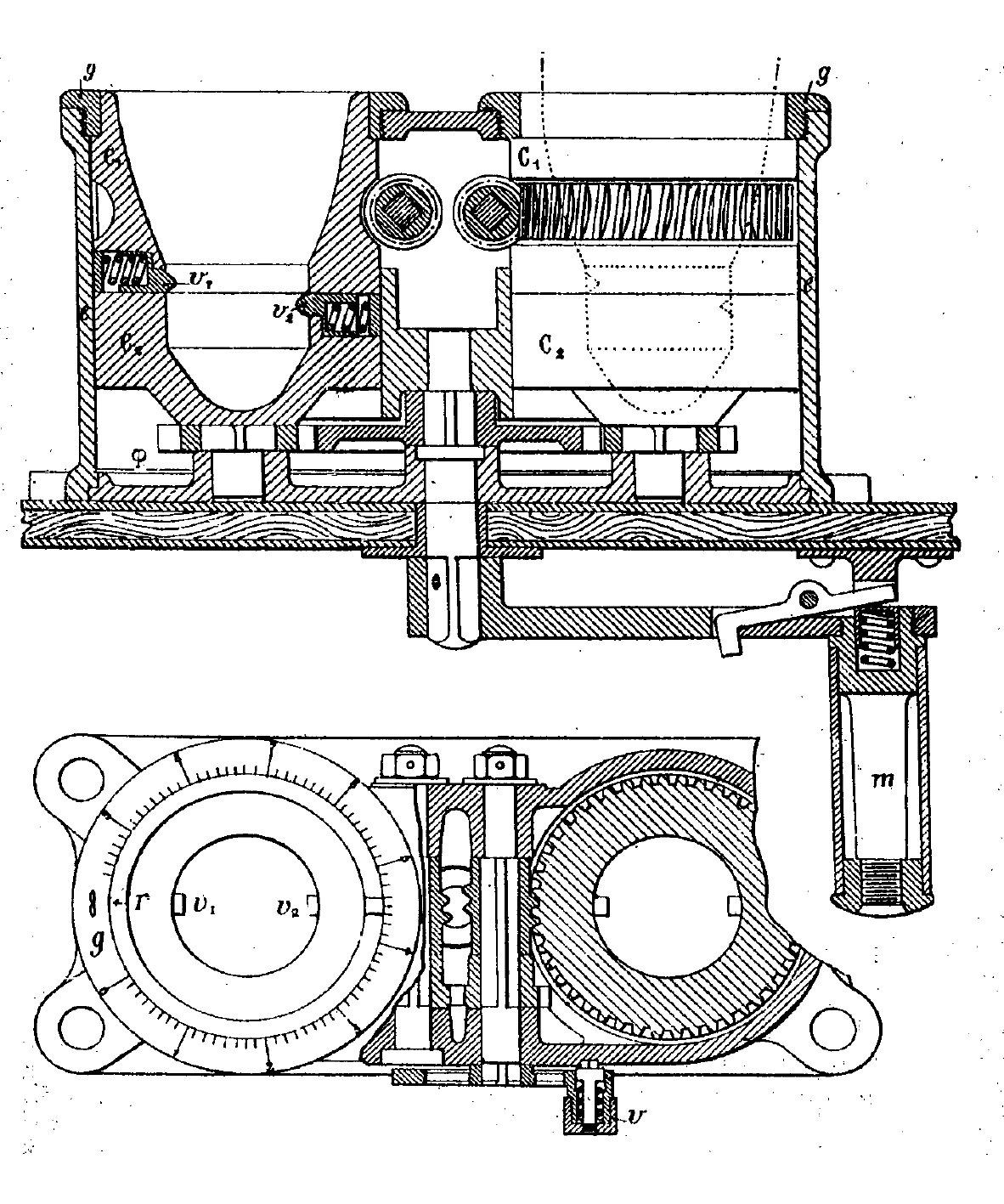
Schneider double mechanical fuze-setter for field
gun. It was composed by a box with two cylindrical casing e, containing the wreaths C1 and C2, provided with two little spring bolts v1 and v2 and included
between the frame φ and the
graduated cap g. On the inside the
two wreaths were shaped according with the shape of the nose of the fuzed
shell. They could turn around their axis, respectively acting on the
handwheel v and rotating the crank m. The transmission was arranged so
that the angular displacement had the same extent both on the right and on
the left side, allowing the setting of two different fuzes at the same time. At first the
shells were placed vertically in the casings, with the heads down. Acting on
the handwheel v, the marks r of the wreath C1 were put in front of the division engraved on the cap g; the spring bolts v1 and v2 took the correct angular deviation and fell in the
corresponding grooves of the fuze. Then rotating the crank m, they were engaged in the plugs (N° 20a in the Schneider fuze)
screwed on the external surface of the fuze cap, and the bottom composition
ring (N° 2) turned of the desired
angle, adjusting both the fuzes at the same setting. The time of burst could
be modify even at the last minute by means of the handwheel v. |
|
|
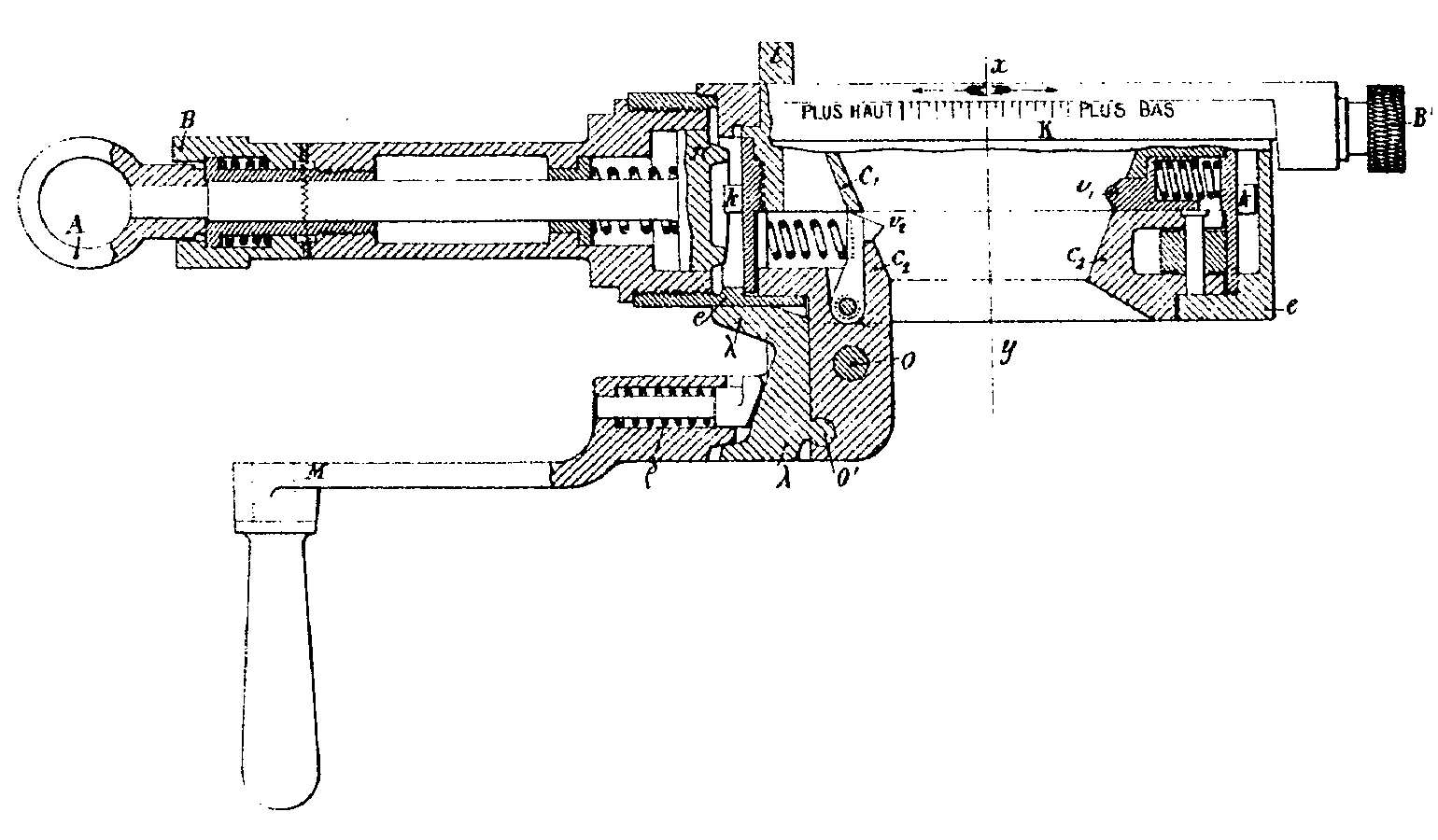
Schneider single mechanical fuze-setter for heavy
gun. The details of the mechanism were similar in many functional respects
to the double fuze-setter described above, but it could set only one shell at
a time. The spring
bolts v1 and v2 were placed at the required angular distance turning the
wreath C1 by means of the milled
knob B, whose motion directed the
plate π carrying in
relief a spiral which was engaged in the toothed arc k, or disengaging by means of the ring A the spiral to bring by hand, through of the lug t, the mark r in front of the desired division. Then the shell was placed on
the fuze-setter as above, and was adjusted at the desired set simply rotating
the wreath C2 of one or two turns,
by means of the crank M. The time
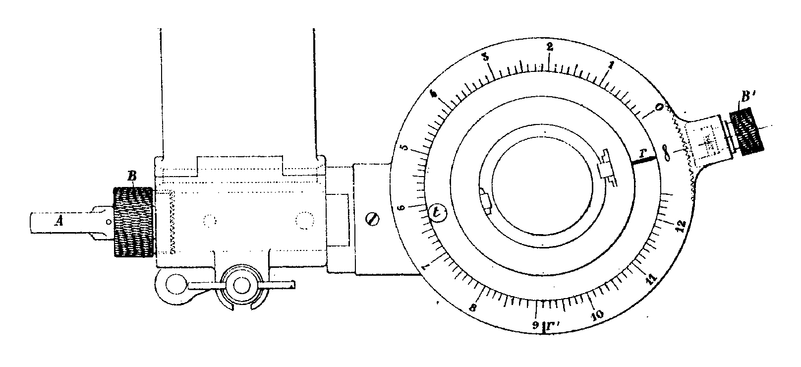
of burst of the fuze could be modify by means of the knob B’, which shifted the mark r’ in front of the corrector K, setting the wreath C2. The
fuze-setter was equipped with a special safety device, to block the rotation
around the axis xy. The crank M was blocked by the toe of the safety
latch λ, which
entered in a groove cut in the casing e.
So, to turn the wreath C2, it was
necessary to press down the crank, which could pivot around the axis o (see the dotted line in the second
picture below). After every turn, the spring ρ, acting under
the pivoting point o’ safety latch,
pulled up the latch, preventing to make another turn. SOURCE : CUREY. Charles Marie : “L’artillerie Schneider-Canet
à l’Exposition universelle de |
|
|
|
|
|
|
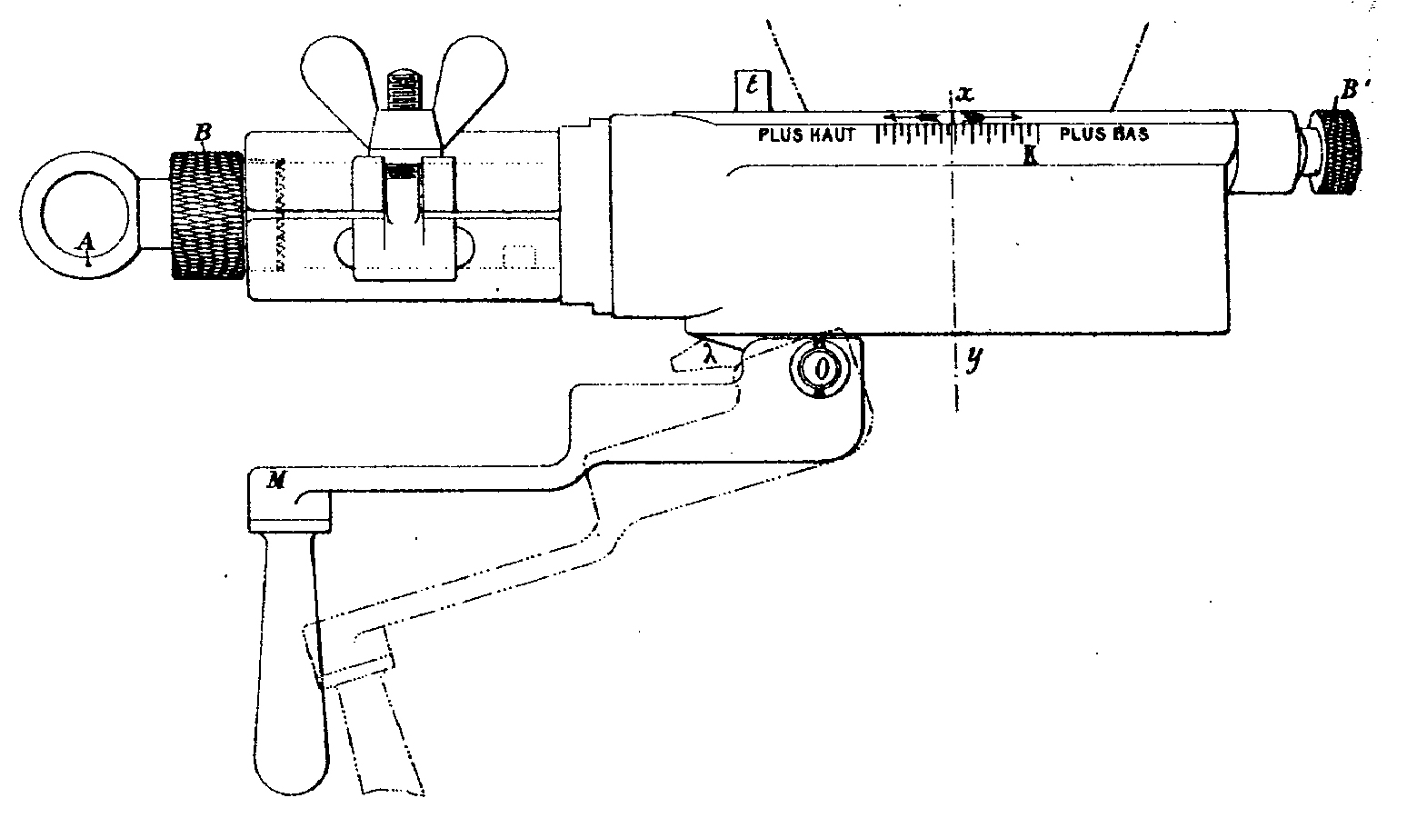
Schneider single mechanical fuze-setter for heavy
gun |
||